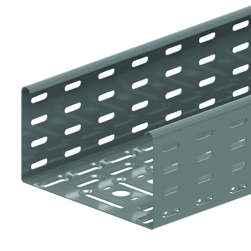
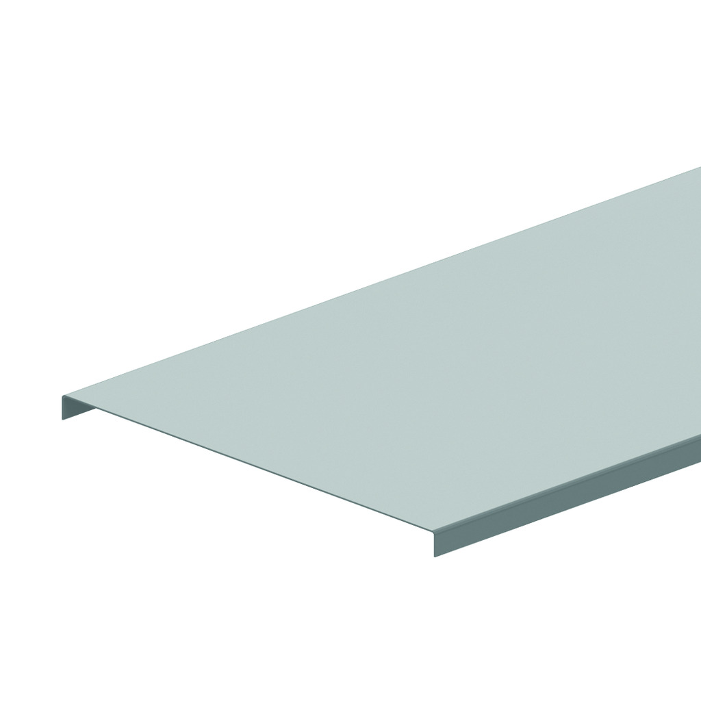
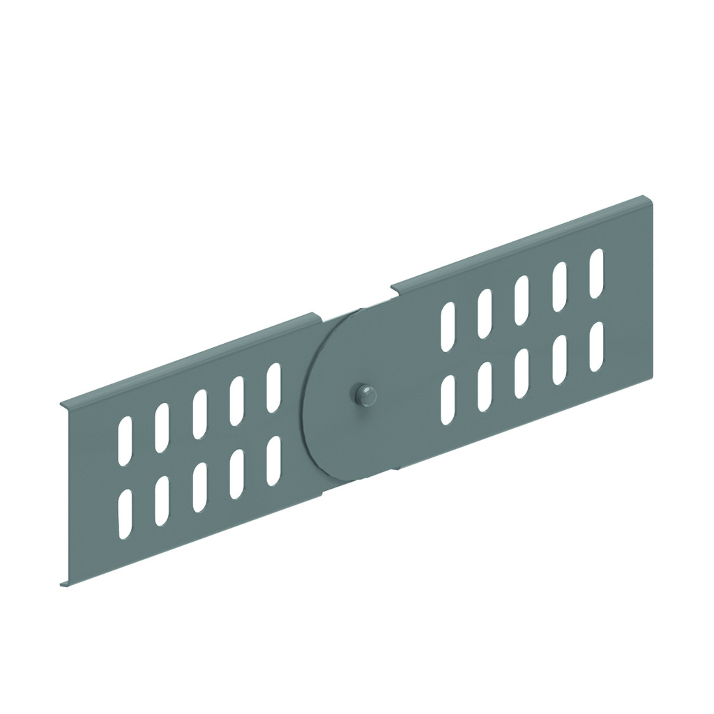
Perforated cable tray - KBS110
Alternative perforation
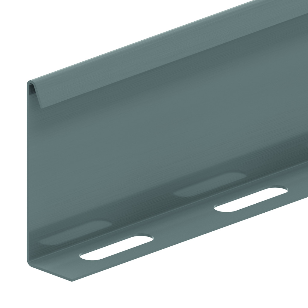
Return flanges
ETIM: EC000047
Return flanges
ETIM: EC000047
| Reference | Finish |
mm |
mm |
mm |
mm |
kg m |
Unit | |
| KBS110.100.100 | SZ | 110 | 100 | 1.00 | 3000 | 1.980 | 24 | M |
| KBS110.150.100 | SZ | 110 | 150 | 1.00 | 3000 | 2.290 | 24 | M |
| KBS110.200.100 | SZ | 110 | 200 | 1.00 | 3000 | 2.576 | 24 | M |
| KBS110.300.100 | SZ | 110 | 300 | 1.00 | 3000 | 3.168 | 24 | M |
| KBS110.400.100 | SZ | 110 | 400 | 1.00 | 3000 | 3.751 | 24 | M |
| KBS110.500.125 | SZ | 110 | 500 | 1.25 | 3000 | 6.030 | 24 | M |
| KBS110.600.125 | SZ | 110 | 600 | 1.25 | 3000 | 6.840 | 24 | M |
| ZMKBS110.100.100 | DF | 110 | 100 | 1.00 | 3000 | 1.980 | 24 | M |
| ZMKBS110.150.100 | DF | 110 | 150 | 1.00 | 3000 | 2.290 | 24 | M |
| ZMKBS110.200.100 | DF | 110 | 200 | 1.00 | 3000 | 2.576 | 24 | M |
| ZMKBS110.300.100 | DF | 110 | 300 | 1.00 | 3000 | 3.168 | 24 | M |
| ZMKBS110.400.100 | DF | 110 | 400 | 1.00 | 3000 | 3.751 | 24 | M |
| ZMKBS110.500.125 | DF | 110 | 500 | 1.25 | 3000 | 7.040 | 24 | M |
| ZMKBS110.600.125 | DF | 110 | 600 | 1.25 | 3000 | 8.110 | 24 | M |