Go to Vergokan homepage

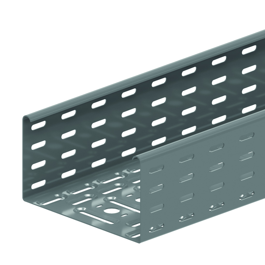
Perforated cable tray - KBS110.6

Alternative perforation
Return flanges
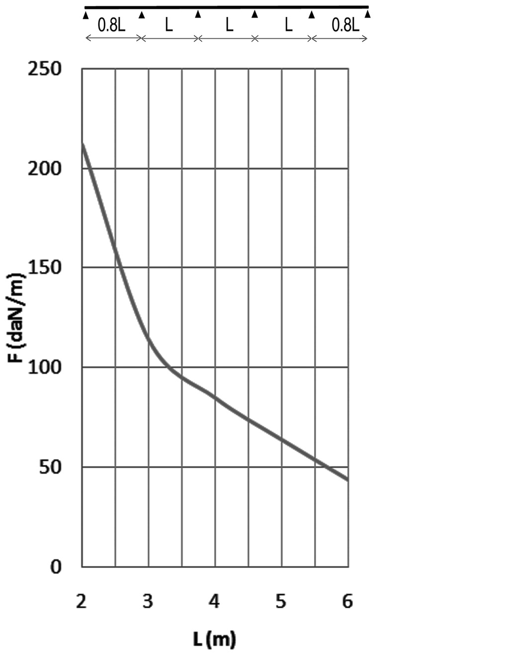
Support distance up to 6 meter


ETIM: EC000047


HD Reference
mm

mm

mm

mm
kg
m
Stock Unit
HD KBS110.200.150.6 110 200 1.5 6000 4.300 24 v M
HD KBS110.300.150.6 110 300 1.5 6000 5.280 24 v M
HD KBS110.400.150.6 110 400 1.5 6000 6.250 24 v M
HD KBS110.500.150.6 110 500 1.5 6000 7.230 24 v M
HD KBS110.600.150.6 110 600 1.5 6000 8.210 24 v M

Standard finish

  • Standard finish Pre-galvanised

Optional finish

  • Optional finish Hot-dip galvanised
  • Optional finish Coating
CHARACTERISTICS
Embedded perforations for:
- extra load capacity
- better aeration
- better stability
- better condensation drainage

Alternative perforations for:
- better fixing to supports
- very useful for attaching cables.
TECHNICAL INFORMATION
The perforation scheme differs according to the width.
Alternative perforation beginning at 200 mm.
Round holes of Ø 16 mm and Ø 19.5 mm provided as opening for the fitting of a gland.

Technical info

Product datasheet

Questions?

For more info, please contact

vergokanexport@atkore.com
+32 55 31 83 35

Load diagram

KBS110.6 LOAD DIAGRAM
This diagram illustrates the permissible uniformly distributed loads applied to multiple supports. They comply with IEC 61537 with connection in the centre of the span and the end span = 0,8 x the span. For widths of 300 mm and up, it is advised to use a stiffening plate. For span distances > 4 meters, couple the cable trays with KPW.

F = max. admissible load (daN/m)
L = support distance (m)
Max. deflection (m) = L/100