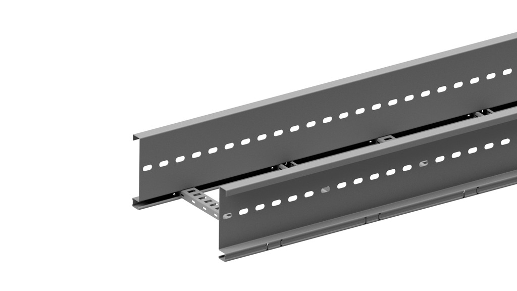
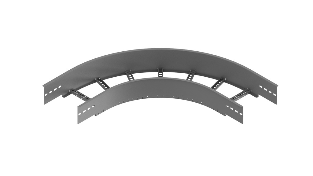
Cable ladder height 200 - KLW
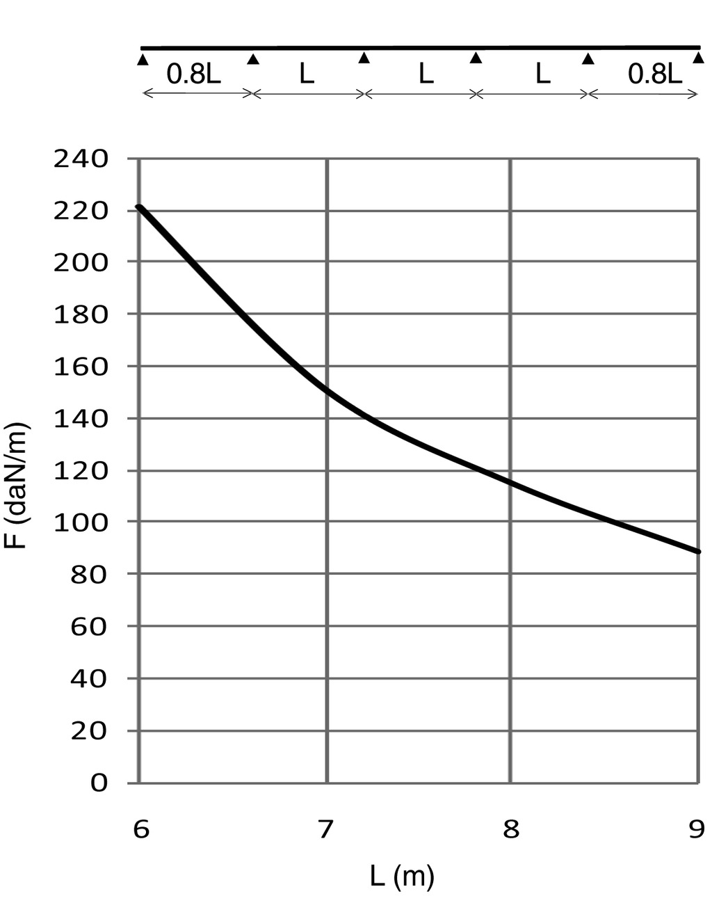
Cable ladder for large support distances up to 9 metres
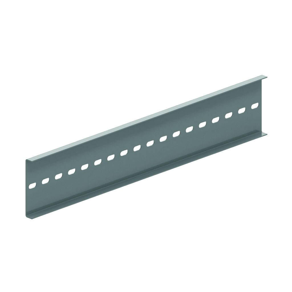
Perforated C datarungs 41x21
Usable inner height: 177 mm
Rung distance: 300 mm
To order: Length 3000 mm
To order: Width 700 - 1200 mm (increments of 100 mm)
ETIM: EC000854
Perforated C datarungs 41x21
Usable inner height: 177 mm
Rung distance: 300 mm
To order: Length 3000 mm
To order: Width 700 - 1200 mm (increments of 100 mm)
ETIM: EC000854
| Reference | Finish |
mm |
mm |
mm |
mm |
kg m |
Unit | |
| KLW200 | SZ | 200 | 218 | 2 | 6000 | 9.873 | 36 | M |
| KLW300 | SZ | 200 | 318 | 2 | 6000 | 10.129 | 36 | M |
| KLW400 | SZ | 200 | 418 | 2 | 6000 | 10.385 | 36 | M |
| KLW500 | SZ | 200 | 518 | 2 | 6000 | 10.641 | 36 | M |
| KLW600 | SZ | 200 | 618 | 2 | 6000 | 10.897 | 36 | M |
| KLW800 | SZ | 200 | 818 | 2 | 6000 | 11.409 | 36 | M |
| KLW1000 | SZ | 200 | 1018 | 2 | 6000 | 11.921 | 36 | M |
| ZMKLW200 | DF | 200 | 218 | 2 | 6000 | 9.873 | 36 | M |
| ZMKLW300 | DF | 200 | 318 | 2 | 6000 | 10.129 | 36 | M |
| ZMKLW400 | DF | 200 | 418 | 2 | 6000 | 10.385 | 36 | M |
| ZMKLW500 | DF | 200 | 518 | 2 | 6000 | 10.641 | 36 | M |
| ZMKLW600 | DF | 200 | 618 | 2 | 6000 | 10.897 | 36 | M |
| ZMKLW800 | DF | 200 | 818 | 2 | 6000 | 11.409 | 36 | M |
| ZMKLW1000 | DF | 200 | 1018 | 2 | 6000 | 11.921 | 36 | M |