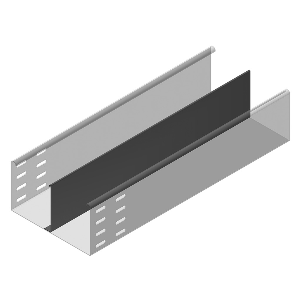
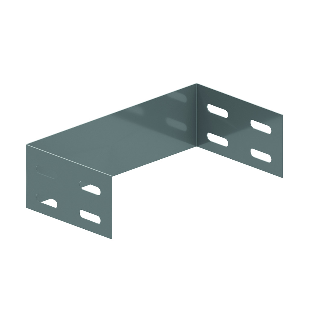
KG with SIN - KG110S
Not perforated
Return flanges
To order: Height 85 mm
ETIM: EC000047
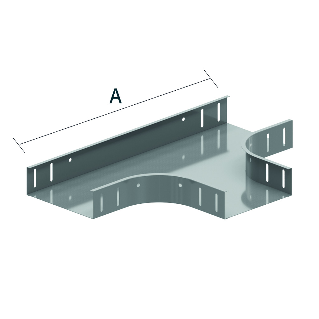
Return flanges
To order: Height 85 mm
ETIM: EC000047
| Reference |
mm |
mm |
mm |
mm |
kg m |
Unit | |
| KG110.100.150S12 | 110 | 100 | 1.50 | 3000 | 4.820 | 30 | M |
| KG110.100.150S13 | 110 | 100 | 1.50 | 3000 | 4.820 | 30 | M |
| KG110.150.150S12 | 110 | 150 | 1.50 | 3000 | 5.410 | 30 | M |
| KG110.150.150S13 | 110 | 150 | 1.50 | 3000 | 5.410 | 30 | M |
| KG110.150.150S23 | 110 | 150 | 1.50 | 3000 | 6.230 | 30 | M |
| KG110.200.150S12 | 110 | 200 | 1.50 | 3000 | 6.000 | 30 | M |
| KG110.200.150S13 | 110 | 200 | 1.50 | 3000 | 6.000 | 30 | M |
| KG110.200.150S23 | 110 | 200 | 1.50 | 3000 | 6.820 | 30 | M |
| KG110.300.150S12 | 110 | 300 | 1.50 | 3000 | 7.180 | 30 | M |
| KG110.300.150S13 | 110 | 300 | 1.50 | 3000 | 7.180 | 30 | M |
| KG110.300.150S23 | 110 | 300 | 1.50 | 3000 | 8.000 | 30 | M |
| KG110.400.150S12 | 110 | 400 | 1.50 | 3000 | 8.360 | 30 | M |
| KG110.400.150S13 | 110 | 400 | 1.50 | 3000 | 8.360 | 30 | M |
| KG110.400.150S23 | 110 | 400 | 1.50 | 3000 | 9.180 | 30 | M |
| KG110.500.150S12 | 110 | 500 | 1.50 | 3000 | 9.530 | 30 | M |
| KG110.500.150S13 | 110 | 500 | 1.50 | 3000 | 9.530 | 30 | M |
| KG110.500.150S23 | 110 | 500 | 1.50 | 3000 | 10.350 | 30 | M |
| KG110.600.150S12 | 110 | 600 | 1.50 | 3000 | 10.710 | 30 | M |
| KG110.600.150S13 | 110 | 600 | 1.50 | 3000 | 10.710 | 30 | M |
| KG110.600.150S23 | 110 | 600 | 1.50 | 3000 | 11.530 | 30 | M |