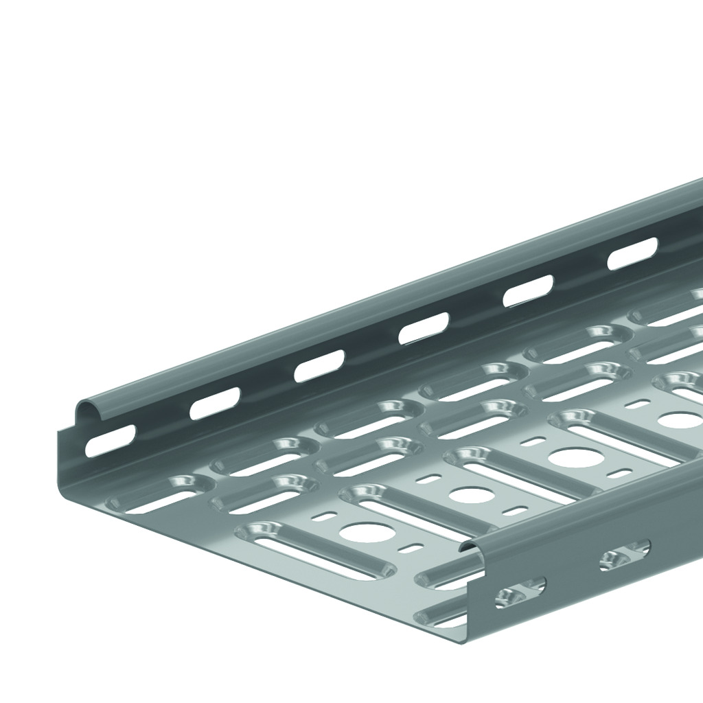
Cable tray with interlocking ends - KBSI35
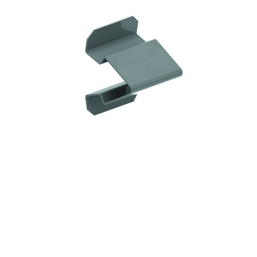
Interlocking ends
Alternative perforations
Return flanges
ETIM: EC000047
Alternative perforations
Return flanges
ETIM: EC000047
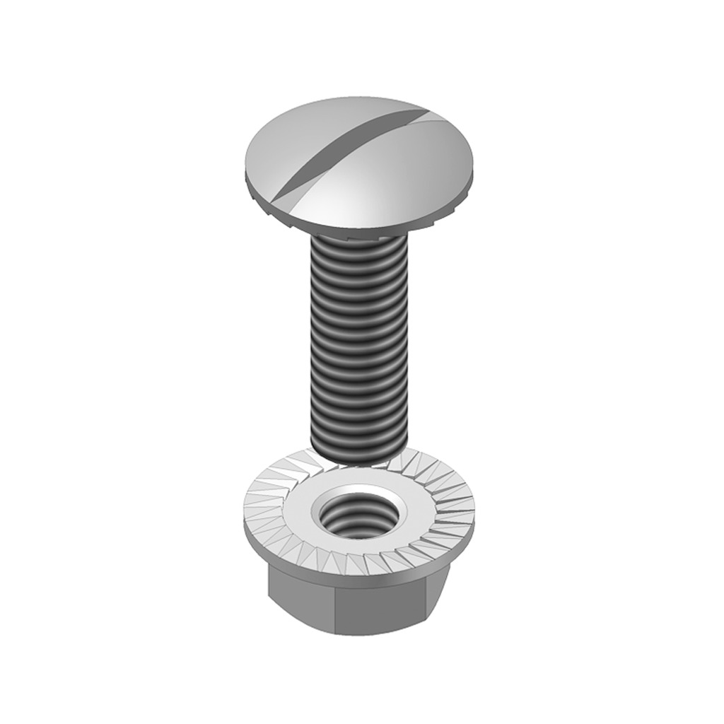
| Reference |
mm |
mm |
mm |
mm |
kg m |
Unit | |
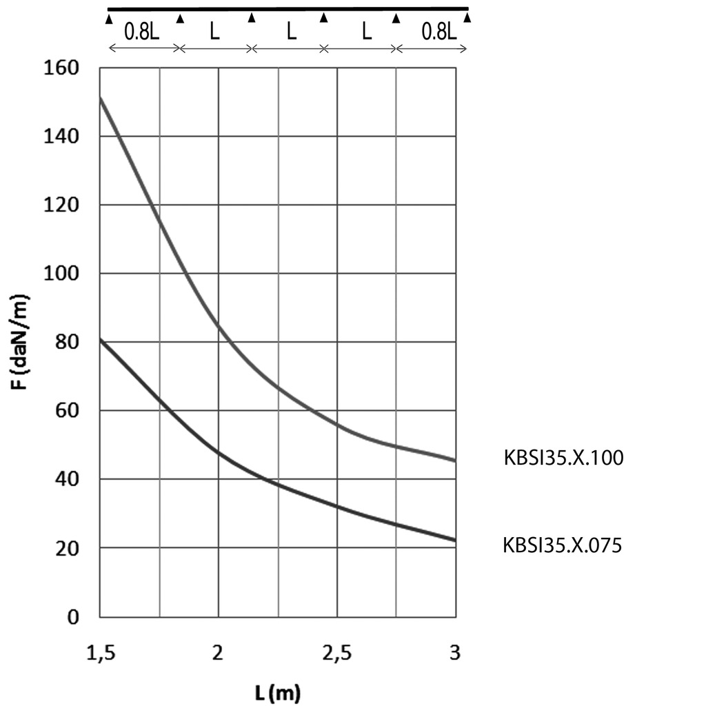
| KBSI35.100.075 | 35 | 100 | 0.75 | 3000 | 0.930 | 60 | M |
| KBSI35.075.075 | 35 | 75 | 0.75 | 3000 | 0.810 | 60 | M |
| KBSI35.150.075 | 35 | 150 | 0.75 | 3000 | 1.170 | 60 | M |
| KBSI35.200.075 | 35 | 200 | 0.75 | 3000 | 1.420 | 60 | M |
| KBSI35.300.075 | 35 | 300 | 0.75 | 3000 | 1.910 | 60 | M |