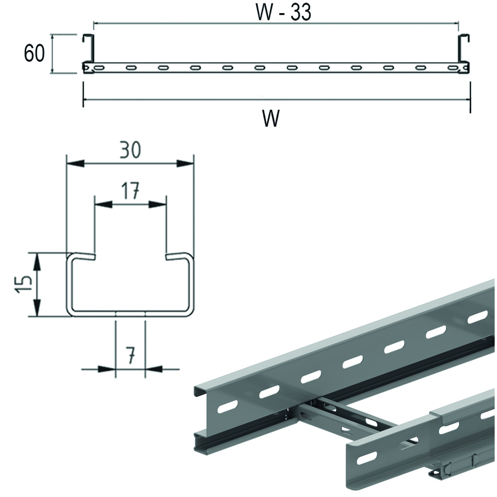
Cable ladder interlocking ends - KLLI60.6
Side walls: perforated S-profile
Perforated C rungs 15x30
Usable inner height: 44 mm
Rung distance: 250 mm
ETIM: EC000854
Perforated C rungs 15x30
Usable inner height: 44 mm
Rung distance: 250 mm
ETIM: EC000854
| Reference | Finish |
mm |
mm |
mm |
mm |
kg m |
Stock | Unit | |
| KLLI60.150.6 | SZ | 60 | 150 | 1 | 6000 | 2.142 | 30 | M | |
| KLLI60.200.6 | SZ | 60 | 200 | 1 | 6000 | 2.261 | 30 | M | |
| KLLI60.300.6 | SZ | 60 | 300 | 1 | 6000 | 2.499 | 30 | M | |
| KLLI60.400.6 | SZ | 60 | 400 | 1 | 6000 | 2.736 | 30 | M | |
| KLLI60.500.6 | SZ | 60 | 500 | 1 | 6000 | 2.974 | 30 | M | |
| KLLI60.600.6 | SZ | 60 | 600 | 1 | 6000 | 3.212 | 30 | M | |
| KLLI60.800.6 | SZ | 60 | 800 | 1 | 6000 | 3.687 | 30 | M | |
| HDKLLI60.150.6 | - | 60 | 150 | 6000 | 2.142 | 6 | M | ||
| HDKLLI60.200.6 | - | 60 | 200 | 6000 | 2.261 | 6 | M | ||
| HDKLLI60.300.6 | - | 60 | 300 | 6000 | 2.499 | 6 | M | ||
| HDKLLI60.400.6 | - | 60 | 400 | 6000 | 2.736 | 6 | M | ||
| HDKLLI60.500.6 | - | 60 | 500 | 6000 | 2.974 | 6 | M | ||
| HDKLLI60.600.6 | - | 60 | 600 | 6000 | 3.212 | 6 | M | ||
| HDKLLI60.800.6 | - | 60 | 800 | 6000 | 3.687 | 6 | M | ||
| ZMKLLI60.150.6 | DF | 60 | 150 | 1 | 6000 | 2.142 | 30 | v | M |
| ZMKLLI60.200.6 | DF | 60 | 200 | 1 | 6000 | 2.261 | 30 | v | M |
| ZMKLLI60.300.6 | DF | 60 | 300 | 1 | 6000 | 2.499 | 30 | v | M |
| ZMKLLI60.400.6 | DF | 60 | 400 | 1 | 6000 | 2.736 | 30 | v | M |
| ZMKLLI60.500.6 | DF | 60 | 500 | 1 | 6000 | 2.974 | 30 | v | M |
| ZMKLLI60.600.6 | DF | 60 | 600 | 1 | 6000 | 3.212 | 30 | v | M |
| ZMKLLI60.800.6 | DF | 60 | 800 | 1 | 6000 | 3.687 | 30 | M |